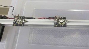
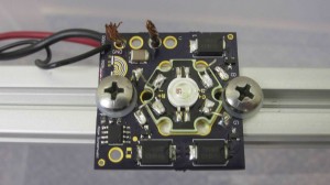
I assembled two of the RGB LED boards and mounted them on some 20mm extruded aluminium for testing. Here is picture of them on the aluminum, and a closeup of the assembly.
I found that 6-32 nylon screws are almost a perfect fit to hold down the LED, but I need to find something a little bit better or modify the PCB layout to get a better fit. I also found that the head size on all the screws are way to big and take up a disproportionate amount of PCB real estate. I am thinking the best solution would be to get rid of the PCB mounting screws at the top and bottom of the board, and find an extruded aluminum insert nut / bolt that fits through the LED holes. I really want to keep the LED metal core PCB tight against the PCB with a dab of thermal paste for heat dissipation, these things give off a ton of heat.
In addition to hole size and screw seletion, I need to find a good solution for bringing power and signal to the board. At maximum continous current consumption, each board will consume about 1050mA plus 54mA (3*18 for each PNP) driving current. The total current consumption should be just under 1200mA, and I want to be able to put 10 to 15 of these on each strip. Ideally My power solution will be able to supply 20 Amps to the boards. I am not a fan of splice power connections, and what I really want is to place two connector jacks at either side of the board for the supply voltage, ground, and data in / out (3 wires between each board). Unfortunatley at 1 oz. copper fill, this requires a trace width of about 3×1 inches at 20 amps for a 5 degree raise in temperature (There is a useful set of tools for this at www.circuitcalculator.com). It seems like my best for a reasonably priced solution is screw hole crimps / terminals, but its not quite what I want.
I don’t have any pictures of the LED tests yet, but so far they are not performing quite as well as I want. I’ve noticed the pnp’s starting to smoke (even though they are rated at 1 Amp) when I have the system running at full capacity. I’m not sure if this is an issue of too much voltage applied across the transistor during saturation due to the linear current regulator, the frequency switching power loss (integral of Vsw * Isw over the switching period), or side effect of using the ws2811 to pull current through the pnp without a base resistor.
The code so far:
LED Control: I modified some code found at http://forum.43oh.com/topic/2852-ws2811-led-controller-driver/ for an MSP430 launchpad (I have a bunch of these lying around). It just cycles through various modes, ranging from a combination of colors on all LEDS to and a moving wave of color traversing the strip. The code uses an assembly routine to write the data to the strip due to the odd timing constraints that the ws2811 demands. For the ardiono guys out there,PRJC has an incredible library at https://www.pjrc.com/teensy/td_libs_OctoWS2811.html. They even manage to get video playing on a huge LED array.
LCD / UI:
I am also working on a basic proof of concept UI. It will display an array of RGB bar graph of color content in each LED (I’ve written a basic bar graph routine to create a large number of bar graphs and plot them in a window on the LCD. I also plan to implement an LED selector interface and Up/Down controls for each color. This is more of a proof of concept for the LED control. The bar graph array might be useful, but I don’t feel it would be practical to select LED’s individually and control their color content. I found that the msp430 was not quite powerful enough to properly display a fluid animation on the LCD i’m using (adafruit’s 2.2″ TFT with an ILI9340 configured in serial mode). I moved my code over to a Tiva launchpad (ARM M4) and the animated bar graphs are looking quite swell.
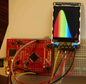
Here is a picture of the of the bar graph interface test code I made. I display an array of colors indexed from the rainbow. It turns out it is actually fairly complicated to get a rainbow colored gradient of RGB color codes, so I ended up using various color space conversion techniques to go from wavelength to RGB percentage in matlab. I then converted the RGB values to to binary arrays of [0b5 Red , 0b5 Green, 0b5 Blue] and then to the hex equivalent. I then just plucked out an evenly spaced array of 40 codes to create my color lookup table. I dont have a video of the animation, but the sin wave shifts to the right and the colors shift to the left.


