Project Overview
Goal: Drive high power RGB LED pixels (350mA each channel) with control over each pixel and color.
The LED: I bought 15 of these a few years ago , http://www.dx.com/en/p/3w-led-emitter-on-star-multicolored-rgb-4530 .
It is a high power RGB LED on a metal core PCB.
Here are the specs:
- Red: 2.5V ~ 3.0V, 350mA
- Green: 3.2V ~ 3.8V, 350mA
- Blue: 3.2V ~ 3.8V, 350mA
After playing with a quick prototype proof of concept, I realized the + and – symbols are mislabeled, they should be swapped. To control the LEDs I chose the WS2811. It sinks a constant 18.5mA per channel with PWM control signals received and re transmitted by each chip for easy daisy chaining. While not a perfect solution, the WS2811 fairly popular. Based on the number of platforms on which people have published code libraries for this controller, it seemed like an excellent choice.
The first revision uses the WS2811 constant current source to drive pnp bjt’s that switch each led channel on and off. For current regulation in each LED channel, I have left the option to either use a constant current regulator or a resistor. The constant current regulators aren’t working as well as I had hoped. The plan for the next revision is to use a micro controller with WS2811 command set compatibility, and implement a current controlled buck converter on each channel. Between the costs of the WS2811, bjt, and current regulator, I don’t expect the efficient buck converter to be much more expensive.
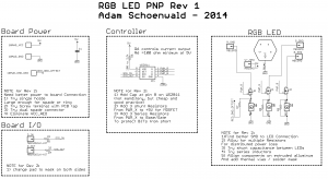
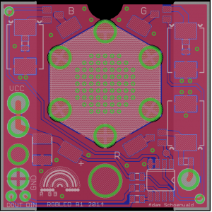
Take a look at the schematic and layout here:
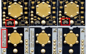
Here is a scan of 3 boards. Besides the obvious mistake of RoyGBiv, where my blue and indigo on the rainbow need to be swapped, you can see the silk screen offset. It turns out that the fab for OshPark has a solder mask and silkscreen tolerance of 5 mil and 3 mil respectively. These are from the copper plane, so it is possible to actually end up with a mask to silk error of 8 mil worst case.


